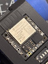
CodeCell is designed to be easy to set up and use, but like any microcontroller, issues can arise. This guide will help you troubleshoot and debug CodeCell effectively.
Before troubleshooting, make sure you’re using the latest versions of:
To update:
To make programming easier, the CodeCell library provides a variety of functions for initializing, reading, and managing sensors and power. Here’s everything you need to know about setting up your device and its library.
Inside the box, you’ll find:
Plug in a USB-C cable, and CodeCell will:
Download the latest version from the official Arduino website.
https://dl.espressif.com/dl/package_esp32_index.json
The first step is to initialize the CodeCell using:
myCodeCell.Init(SENSOR_MACRO);
Available Macros:
You can combine multiple macros using the +
operator:
myCodeCell.Init(LIGHT + MOTION_ACCELEROMETER + MOTION_GYRO);
myCodeCell.Init(SENSOR_MACRO);
Hope this has helped you identify the root cause. If you're still facing the issue, don’t hesitate to reach out - we’d be glad to help!
Bluetooth Low Energy (BLE) is a powerful way to communicate wirelessly between your CodeCell and other devices like smartphones, tablets, and even other microcontrollers. In this guide, we’ll set up BLE on CodeCell, allow it to receive commands from a BLE client, and control its RGB LED based on the received data.
BLE is an energy-efficient version of Bluetooth that allows devices to exchange small amounts of data with low power consumption. Here are it's key concepts:
Before we start testing, your need to download an app to send BLE data on your smartphone. So start by downloading a BLE scanner app:
To make CodeCell advertise itself as a BLE device, we need to initialize BLE, create a service and characteristic, and start advertising.
This code creates a BLE server, advertises a service, and sets up a characteristic that can be read and written by a connected device. The CodeCell will receive the button characteristic and control its onboard RGB LED:
#include <BLEDevice.h>
#include <BLEUtils.h>
#include <BLEServer.h>
#include <BLE2902.h>
#include <CodeCell.h>
CodeCell myCodeCell;
BLECharacteristic *pButtonCharacteristic = NULL;
#define BUTTON_UUID "abcd1234-abcd-1234-abcd-123456789012"
class MyServerCallbacks : public BLEServerCallbacks {
void onConnect(BLEServer *pServer) override {
Serial.println("BLE Connected");
delay(1000);
}
void onDisconnect(BLEServer *pServer) override {
Serial.println("BLE Disconnected");
delay(500);
BLEDevice::startAdvertising(); // Restart advertising
}
};
// Callback class for handling button writes
class ButtonCallback : public BLECharacteristicCallbacks {
void onWrite(BLECharacteristic *pCharacteristic) override {
String value = pCharacteristic->getValue();
if (value.length() > 0) {
int buttonState = value[0];
Serial.print("Button State: ");
Serial.println(buttonState);
if (buttonState == 1) {
myCodeCell.LED(255, 0, 0); // Red LED when button is 1
} else {
myCodeCell.LED(0, 255, 0); // Green LED when button is not 1
}
}
}
};
void setup() {
Serial.begin(115200);
myCodeCell.Init(LIGHT); // Initializes the light sensor
BLEDevice::init("CodeCell_BLE"); // Set BLE device name
BLEServer *bleServer = BLEDevice::createServer();
bleServer->setCallbacks(new MyServerCallbacks());
BLEService *bleService = bleServer->createService(BLEUUID("12345678-1234-5678-1234-56789abcdef0"));
// Create BLE characteristic for button state
pButtonCharacteristic = bleService->createCharacteristic(
BUTTON_UUID,
BLECharacteristic::PROPERTY_READ | BLECharacteristic::PROPERTY_WRITE
);
pButtonCharacteristic->addDescriptor(new BLE2902());
pButtonCharacteristic->setCallbacks(new ButtonCallback());
bleService->start();
BLEAdvertising *pAdvertising = BLEDevice::getAdvertising();
pAdvertising->addServiceUUID("12345678-1234-5678-1234-56789abcdef0");
BLEDevice::startAdvertising();
}
void loop() {
// No need to continuously check, LED updates only on BLE write
}
"CodeCell_BLE"
."CodeCell_BLE"
in the BLE Scanner app.BUTTON_UUID
) and send the value:
1
→ LED turns red 🔴0
→ LED turns green 🟢Next we'll define a new BLE characteristic that allows CodeCell to send sensor values to a connected device.
#include <BLEDevice.h>
#include <BLEUtils.h>
#include <BLEServer.h>
#include <BLE2902.h>
#include <CodeCell.h>
CodeCell myCodeCell;
BLECharacteristic *pSensorCharacteristic = NULL;
#define SENSOR_UUID "abcd5678-abcd-5678-abcd-56789abcdef0"
class MyServerCallbacks : public BLEServerCallbacks {
void onConnect(BLEServer *pServer) override {
Serial.println("BLE Connected");
delay(1000);
}
void onDisconnect(BLEServer *pServer) override {
Serial.println("BLE Disconnected");
delay(500);
BLEDevice::startAdvertising(); // Restart advertising
}
};
void setup() {
Serial.begin(115200);
myCodeCell.Init(LIGHT); // Initialize light and proximity sensor
BLEDevice::init("CodeCell_BLE"); // Name the BLE device
BLEServer *bleServer = BLEDevice::createServer();
bleServer->setCallbacks(new MyServerCallbacks());
BLEService *bleService = bleServer->createService(BLEUUID("12345678-1234-5678-1234-56789abcdef0"));
// Create BLE characteristic for sensor data
pSensorCharacteristic = bleService->createCharacteristic(
SENSOR_UUID,
BLECharacteristic::PROPERTY_READ | BLECharacteristic::PROPERTY_NOTIFY
);
pSensorCharacteristic->addDescriptor(new BLE2902());
bleService->start();
BLEAdvertising *pAdvertising = BLEDevice::getAdvertising();
pAdvertising->addServiceUUID("12345678-1234-5678-1234-56789abcdef0");
BLEDevice::startAdvertising();
}
void loop() {
if (myCodeCell.Run(10)) { // Read every 100ms (10Hz)
uint16_t proximity = myCodeCell.Light_ProximityRead();
Serial.print("Proximity: ");
Serial.println(proximity);
// Convert proximity value to string and send over BLE
String proximityStr = String(proximity);
pSensorCharacteristic->setValue(proximityStr.c_str());
pSensorCharacteristic->notify(); // Notify connected device
}
}
SENSOR_UUID
) that clients can read and get real-time updates:
We convert the number to a string and send it to the BLE client.
Now that CodeCell is sending proximity sensor data over BLE, you can view it on a phone.
"CodeCell_BLE"
and connectSENSOR_UUID
)
Move an object near the sensor and see how values change!
Now that you can control CodeCell via BLE, try:
The CodeCell module, powered by the ESP32-C3, has built-in Wi-Fi capabilities that allow it to connect to the internet, communicate with other devices, and even host a small web server. Whether you're a beginner or an experienced maker, this guide will help you get started with Wi-Fi on CodeCell.
Wi-Fi allows your CodeCell to wirelessly connect to the internet or a local network. This means you can:
Now, let's go step by step to connect CodeCell to Wi-Fi.
To connect your CodeCell to a Wi-Fi network, you need to provide the network name (SSID) and password. Let's use the Arduino IDE to write a simple program that connects CodeCell to Wi-Fi.
#include <WiFi.h>
#include <CodeCell.h>
CodeCell myCodeCell;
const char* ssid = "your_SSID"; // Replace with your Wi-Fi name
const char* password = "your_PASSWORD"; // Replace with your Wi-Fi password
void setup() {
Serial.begin(115200); // Start the Serial Monitor
myCodeCell.Init(LIGHT); // Set up CodeCell's light sensor
WiFi.begin(ssid, password); // Connect to Wi-Fi
Serial.print("Connecting to Wi-Fi");
while (WiFi.status() != WL_CONNECTED) {
delay(500);
Serial.print("."); // Print dots while connecting
}
Serial.println("\nConnected!");
Serial.print("IP Address: ");
Serial.println(WiFi.localIP()); // Print the assigned IP address
}
void loop() {
// Run every 10Hz
if (myCodeCell.Run(10)) {
// Your main loop code here
}
}
WiFi.begin(ssid, password);
.Once CodeCell is connected to Wi-Fi, we can make it act like a tiny web server! This means we can control it or display information using a web page.
#include <WiFi.h>
#include <WebServer.h>
#include <CodeCell.h>
CodeCell myCodeCell;
const char* ssid = "your_SSID";
const char* password = "your_PASSWORD";
WebServer server(80);
void handleRoot() {
int proximityValue = myCodeCell.Light_ProximityRead(); // Read proximity sensor
String response = "Welcome to CodeCell Wi-Fi Server!
";
response += "Proximity Value: " + String(proximityValue) + "
";
server.send(200, "text/html", response);
}
void setup() {
Serial.begin(115200);
myCodeCell.Init(LIGHT); // Set up CodeCell's light sensor
WiFi.begin(ssid, password);
while (WiFi.status() != WL_CONNECTED) {
delay(500);
Serial.print(".");
}
Serial.println("\nConnected to Wi-Fi");
Serial.print("IP Address: ");
Serial.println(WiFi.localIP());
server.on("/", handleRoot);
server.begin();
Serial.println("HTTP server started");
}
void loop() {
if(myCodeCell.Run(10)){
server.handleClient();
}
}
CodeCell can also send data to a web server, such as a cloud service that collects sensor readings.
#include <WiFi.h>
#include <HTTPClient.h>
#include <CodeCell.h>
CodeCell myCodeCell;
const char* ssid = "your_SSID";
const char* password = "your_PASSWORD";
const char* serverName = "http://example.com/data"; // Replace with your server URL
void setup() {
Serial.begin(115200);
myCodeCell.Init(LIGHT); // Set up CodeCell's light sensor
WiFi.begin(ssid, password);
while (WiFi.status() != WL_CONNECTED) {
delay(500);
Serial.print(".");
}
Serial.println("Connected to Wi-Fi");
}
void loop() {
if (myCodeCell.Run(10)) { // Run every 10hz
HTTPClient http;
http.begin(serverName);
int httpResponseCode = http.GET();
Serial.print("HTTP Response code: ");
Serial.println(httpResponseCode);
http.end();
}
}
http://example.com/data
.
Wi-Fi makes CodeCell powerful for IoT projects! Start experimenting, and soon you’ll be building amazing projects!
Ever wondered how your phone knows which direction you’re facing? It’s all thanks to a magnetometer! Your CodeCell comes with a BNO085 3-axis magnetometer, which detects magnetic fields in three directions. This allows you to measure heading (direction), detect magnetic interference, and even create a simple digital compass!
A magnetometer measures the Earth's magnetic field along three axes:
By using these values, we can calculate the compass heading (0° to 360°) and determine which direction CodeCell is pointing.
Let’s start by initializing the magnetometer and reading raw magnetic field values.
#include <CodeCell.h>
CodeCell myCodeCell;
float x = 0.0; // Magnetic field on X-axis
float y = 0.0; // Magnetic field on Y-axis
float z = 0.0; // Magnetic field on Z-axis
void setup() {
Serial.begin(115200);
myCodeCell.Init(MOTION_MAGNETOMETER); // Initialize the magnetometer
}
void loop() {
if (myCodeCell.Run(10)) { // Read at 10Hz (every 100ms)
myCodeCell.Motion_MagnetometerRead(x, y, z); // Get magnetometer readings
Serial.print("Mag X: "); Serial.print(x);
Serial.print(" Y: "); Serial.print(y);
Serial.print(" Z: "); Serial.println(z);
}
}
Once you upload the code and open the Serial Monitor, you’ll see values like:
Mag X: 12.4 Y: -7.8 Z: 35.2
What Do These Values Mean?
To build a digital compass, we need to convert X and Y values into an angle using the atan2() function.
#include <CodeCell.h>
#include <math.h> // Needed for atan2 function
CodeCell myCodeCell;
float x = 0.0, y = 0.0, z = 0.0;
void setup() {
Serial.begin(115200);
myCodeCell.Init(MOTION_MAGNETOMETER); // Initialize the magnetometer
}
void loop() {
if (myCodeCell.Run(10)) { // Read at 10Hz
myCodeCell.Motion_MagnetometerRead(x, y, z); // Read magnetometer values
// Calculate heading (angle in degrees)
float heading = atan2(y, x) * (180.0 / M_PI);
// Ensure heading is in the range 0° - 360°
if (heading < 0) {
heading += 360;
}
Serial.print("Compass Heading: ");
Serial.println(heading); // Print heading in degrees
}
}
The heading value (0° to 360°) tells us which direction CodeCell is pointing:
Heading (°) | Direction |
---|---|
0° (or 360°) | North ↑ |
90° | East → |
180° | South ↓ |
270° | West ← |
Try rotating CodeCell and watch the heading change!
We can now light up the LED in different colors based on direction:
#include <CodeCell.h>
#include <math.h>
CodeCell myCodeCell;
float x = 0.0, y = 0.0, z = 0.0;
void setup() {
Serial.begin(115200);
myCodeCell.Init(MOTION_MAGNETOMETER); // Initialize the magnetometer
}
void loop() {
if (myCodeCell.Run(10)) { // Read at 10Hz
myCodeCell.Motion_MagnetometerRead(x, y, z); // Read magnetometer values
// Calculate heading
float heading = atan2(y, x) * (180.0 / M_PI);
if (heading < 0) heading += 360;
Serial.print("Heading: ");
Serial.println(heading);
// Change LED color based on heading
if (heading >= 315 || heading < 45) {
myCodeCell.LED(0, 0, 255); // Blue for North
} else if (heading >= 45 && heading < 135) {
myCodeCell.LED(0, 255, 0); // Green for East
} else if (heading >= 135 && heading < 225) {
myCodeCell.LED(255, 0, 0); // Red for South
} else {
myCodeCell.LED(255, 255, 0); // Yellow for West
}
}
}
Now that you can read magnetometer data and calculate direction, try:
The CodeCell comes with a built-in BNO085 3-axis gyroscope, which can measure angular velocity - how fast CodeCell is rotating around each axis - making it easier to detect directional changes.
Unlike an accelerometer that measures movement in a straight line, a gyroscope detects rotational motion. It tells you how fast CodeCell is spinning in degrees per second (°/s).
Before we can use the gyroscope, we need to initialize it and start reading data.
This code reads the X, Y, and Z angular velocity values and prints them every 100ms.
#include <CodeCell.h>
CodeCell myCodeCell;
float x = 0.0; // Angular velocity around X-axis
float y = 0.0; // Angular velocity around Y-axis
float z = 0.0; // Angular velocity around Z-axis
void setup() {
Serial.begin(115200);
myCodeCell.Init(MOTION_GYRO); // Initialize the gyroscope
}
void loop() {
if (myCodeCell.Run(10)) { // Read at 10Hz (every 100ms)
myCodeCell.Motion_GyroRead(x, y, z); // Get gyro readings
Serial.print("Gyro X: "); Serial.print(x);
Serial.print(" Y: "); Serial.print(y);
Serial.print(" Z: "); Serial.println(z);
}
}
What You'll Notice:
The higher the value, the faster the rotation.
Now, let's detect when CodeCell rotates left or right and change the RGB LED color accordingly.
This program:
#include <CodeCell.h>
CodeCell myCodeCell;
float x = 0.0, y = 0.0, z = 0.0;
const float ROTATION_THRESHOLD = 3.0; // Rotation speed threshold (°/s)
void setup() {
Serial.begin(115200);
myCodeCell.Init(MOTION_GYRO); // Initialize gyroscope
}
void loop() {
if (myCodeCell.Run(10)) { // Read at 10Hz
myCodeCell.Motion_GyroRead(x, y, z); // Get gyroscope values
Serial.print("Gyro Z: ");
Serial.println(z); // Print rotation speed
if (z > ROTATION_THRESHOLD) {
myCodeCell.LED(0, 255, 0); // Turn LED green(rotating right)
}
else if (z < -ROTATION_THRESHOLD) {
myCodeCell.LED(255, 0, 0); // Turn LED red (rotating left)
}
else {
myCodeCell.LED(0, 0, 0); // Turn LED off when not rotating
}
}
}
The gyroscope measures angular velocity in degrees per second (°/s). If the value of Z rotation (yaw) exceeds the threshold, we assume CodeCell is being rotated.
Try changing ROTATION_THRESHOLD
to increase or decrease the sensitivity.
Now that you can track rotation, try:
Inside your CodeCell is a BNO085 3-axis accelerometer, a tiny sensor that measures movement. With just a few lines of code, you can detect shaking and even trigger an LED light when movement is detected! Let's break it down step by step.
An accelerometer measures acceleration - how fast something is speeding up or slowing down. It detects:
It even feels gravity! When CodeCell is still, the Z-axis will show a value close to 9.81 m/s², which is Earth's gravity.
First, let's start by reading real-time movement values from CodeCell's onboard accelerometer. This code will show how much CodeCell is moving in each direction:
#include <CodeCell.h>
CodeCell myCodeCell;
float x = 0.0; // X-axis acceleration
float y = 0.0; // Y-axis acceleration
float z = 0.0; // Z-axis acceleration
void setup() {
Serial.begin(115200);
myCodeCell.Init(MOTION_ACCELEROMETER); // Initialize the accelerometer
}
void loop() {
if (myCodeCell.Run(10)) { // Run at 10 times per second (10Hz)
myCodeCell.Motion_AccelerometerRead(x, y, z); // Read motion values
Serial.print("X: "); Serial.print(x);
Serial.print(" Y: "); Serial.print(y);
Serial.print(" Z: "); Serial.println(z);
}
}
Now, let’s detect when CodeCell is shaken and use the onboard RGB LED to signal it.
This program will turn the LED red if a shake is detected.
#include <CodeCell.h>
#include <math.h> // Needed for square root calculations
CodeCell myCodeCell;
float x = 0.0, y = 0.0, z = 0.0;
const float SHAKE_THRESHOLD = 15.0; // Adjust this value for sensitivity
void setup() {
Serial.begin(115200);
myCodeCell.Init(MOTION_ACCELEROMETER); // Initialize accelerometer
}
void loop() {
if (myCodeCell.Run(10)) { // Check every 100ms (10Hz)
myCodeCell.Motion_AccelerometerRead(x, y, z); // Read accelerometer data
// Calculate total movement strength (vector magnitude)
float totalAcceleration = sqrt(x * x + y * y + z * z);
Serial.print("Total Acceleration: ");
Serial.println(totalAcceleration); // Show acceleration strength
// If the acceleration is stronger than the threshold, it's a shake!
if (totalAcceleration > SHAKE_THRESHOLD) {
Serial.println("Shake detected!");
myCodeCell.LED(255, 0, 0); // Turn LED red
delay(500); // Keep LED on for 0.5 seconds
} else {
//Not shaking
}
}
}
Instead of checking X, Y, and Z separately, we combine them into a single value:
This tells us how much CodeCell is moving overall, no matter the direction. If totalAcceleration
jumps above 15.0, we assume CodeCell is being shaken. The onboard RGB LED turns red for 0.5 seconds to signal the shake.
Now that you can detect movement, here are some fun challenges:
By understanding motion sensing, you're learning the same technology used in smartphones, drones, and rockets! 🚀
The onboard RGB LED on CodeCell can also be controlled programmatically to display different colors based on your project's needs.
With CodeCell’s built-in function, you can set the LED color easily:
myCodeCell.LED(uint8_t r, uint8_t g, uint8_t b);
r
→ Red component (0-255)g
→ Green component (0-255)b
→ Blue component (0-255)This allows full RGB color control for your project's needs.
In this example, the onboard RGB LED turns red when an object is detected within a certain range using the light sensor’s proximity detection.
#include <CodeCell.h>
CodeCell myCodeCell;
void setup() {
Serial.begin(115200); // Set Serial baud rate to 115200. Ensure Tools/USB_CDC_On_Boot is enabled if using Serial
myCodeCell.Init(LIGHT); // Initializes light sensing, including proximity
}
void loop() {
if (myCodeCell.Run(10)) {
// Runs every 100ms to check proximity
uint16_t proximity = myCodeCell.Light_ProximityRead();
// Check if an object is within range
if (proximity > 100) {
myCodeCell.LED(0xFF, 0, 0); // Set LED to Red when proximity is detected
delay(1000); // Keep the LED on for 1 second
} else {
// No action if the object is out of range
}
}
}
Remember that the onboard RGB LED is also used for battery and power status indication. When using myCodeCell.Run()
, the LED may be overridden to reflect charging or battery conditions.
If you want to control the LED without interruptions, you may need to adjust how often myCodeCell.Run()
is called or ensure your LED commands are applied after system updates.
I2C is a widely used protocol for communicating with sensors, displays, and other peripherals. CodeCell simplifies I2C communication by automatically configuring the I2C bus at initialization, so you can start using it right away.
The I2C's SDA and SCL pins are located on the lower side of the CodeCell board.
CodeCell automatically configures I2C in the Init()
function, and this configuration cannot be changed if you plan to use the onboard light and motion sensors, as they are connected to the same I2C bus.
The following onboard sensors are already using I2C, so make sure not to use the same addresses when connecting other I2C devices like displays, additional sensors, or modules:
Sensor | Address |
---|---|
VCNL4040 (Light Sensor) | 0x60 |
BNO085 (IMU - Motion Sensor) | 0x4A |
Note: If a new I2C device has the same address as one of these onboard sensors, they will conflict, and you may get incorrect or no data.
To ensure stable I2C communication, CodeCell has 2kΩ pull-up resistors already connected to the SDA and SCL lines. This means you don’t need to add external pull-ups when using external I2C sensors.
To communicate with an external I2C device, use the standard 'Wire.h' library.
Unlike standard Arduino I2C devices, CodeCell has multiple onboard sensors on the same I2C bus. Calling Wire.endTransmission(false);
ensures the bus stays active, allowing the onboard sensors to function properly.
Wire.beginTransmission(SLAVE_ADDRESS); // Start communication with the device
Wire.write(SLAVE_REG); // Send the register we want to read
Wire.endTransmission(false); // Don't release the bus (needed for onboard sensors)
Wire.requestFrom(SLAVE_ADDRESS, 1); // Request 1 byte from the slave
if (Wire.available()) {
uint8_t data = Wire.read(); // Read received byte
Serial.println(data);
}
CodeCell automatically configures the I2C bus, so no need to manually set it up. It also automatically configures the onboard sensors, while also supporting additional I2C devices!
Analog sensors, potentiometers, and other variable inputs require an Analog-to-Digital Converter (ADC) to be read by a microcontroller. With CodeCell, reading an analog signal is as simple as calling pinADC()
.
pinADC()
To read an analog value, use:
uint16_t myADC = myCodeCell.pinADC(uint8_t pin_num);
pin_num
→ The ADC pin you want to read from (IO1, IO2, or IO3).If you connect a potentiometer to IO2, you can read its position with:
uint16_t potValue = myCodeCell.pinADC(2);
Serial.println(potValue);
Since the maximum voltage on CodeCell’s ADC pins should not exceed 3.3V, you should connect the potentiometer to 3V3 instead of Vo:
3V3 → One end of the potentiometer
GND → Other end of the potentiometer
IO2 → Middle pin of the potentiometer
The onboard microcontroller uses a 2.5V internal voltage reference. This means:
To scale readings properly:
float voltage = (myCodeCell.pinADC(2) / 4095.0) * 2.5;
Serial.println(voltage);
pinADC()
Whether you're reading a potentiometer, sensor, or other analog signals, CodeCell makes ADC reading easy.
Pulse Width Modulation (PWM) is essential for controlling LED brightness, motor speed, and even generating audio signals. With CodeCell, setting up PWM is incredibly simple using the pinPWM()
function. Unlike traditional Arduino PWM that requires predefined pins and extra setup, CodeCell allows you to enable PWM on any of its 6 available pins effortlessly.
pinPWM()
To generate a PWM signal, use:
myCodeCell.pinPWM(uint8_t pin_num, uint16_t pin_freq, uint8_t pin_dutycycle);
pin_num
→ The pin you want to use (any of CodeCell's 6 available GPIOs).pin_freq
→ The frequency of the PWM signal (in Hz).pin_dutycycle
→ The duty cycle (0–100), representing the percentage of time the signal stays HIGH.Let’s say you want to dim an LED connected to pin 3 with a 1 kHz (1000 Hz) frequency and 50% brightness:
myCodeCell.pinPWM(3, 1000, 50);
To make the LED brighter (e.g., 80% brightness):
myCodeCell.pinPWM(3, 1000, 80);
Or to turn it off (0% brightness):
myCodeCell.pinPWM(3, 1000, 0);
pinPWM()
and you're ready to go.This function makes PWM control on CodeCell more flexible and easier than ever. Try it out in your next project!
The CodeCell module makes working with GPIO (Input/Output) pins simpler than ever. While you can still use the traditional Arduino digitalWrite()
and digitalRead()
functions, CodeCell library uses the pinWrite()
and pinRead()
, which automatically handle pin initialization for you.
With CodeCell's optimized functions, you don’t need to manually set the pin mode using pinMode()
. Just call:
myCodeCell.pinWrite(uint8_t pin_num, bool pin_value);
For example, to turn on an LED connected to pin 5:
myCodeCell.pinWrite(5, HIGH);
Or turn it off:
myCodeCell.pinWrite(5, LOW);
Reading a pin state is just as simple:
if (myCodeCell.pinRead(5)) {
// Pin is HIGH, do something
}
The pinRead()
function returns a boolean (true
for HIGH, false
for LOW), making GPIO interactions effortless.
No need for pinMode()
—it’s handled automatically, making your sketches cleaner.
Built-in error detection—if a pin is not available on your CodeCell module, it will issue an error on the Serial Monitor, helping you debug the problem.
These functions make CodeCell's GPIO management more intuitive—whether you're controlling LEDs, buttons, and more!
Power efficiency is crucial for many embedded applications, especially those relying on battery power. In this guide, we explore how to put CodeCell into a low-power sleep mode and wake it up using a proximity sensor.
For applications that require complete power shut-off, you can add a switch in series with the battery. This allows you to manually turn the device on and off. Alternatively, you can put CodeCell into sleep mode and wake up when there is sensor activity.
CodeCell has an average sleep current of 689μA. While this may be higher than some ultra-low-power applications require, we are actively working on optimizing power consumption in the next version while still keeping the same size.
Due to the small size and limited number of pins of the ESP32C3, we could not include a dedicated interrupt pin for the sensors to wake up the device. While a true hardware interrupt would be ideal, you can still put CodeCell into sleep mode by periodically check for sensor activity before waking up.
The following code illustrates how CodeCell enters sleep mode and wakes up when proximity is detected.
#include <CodeCell.h>
CodeCell myCodeCell;
void setup() {
Serial.begin(115200);
delay(60); // Waking up from Sleep - add a small delay for Serial
if (myCodeCell.WakeUpCheck()) {
// Initialize light sensor
while (myCodeCell.Light_Init() == 1) {
delay(1);
myCodeCell.LightReset(); // If sensor not responding, reset it
}
delay(40);
myCodeCell.Light_Read(); // Read value from light sensor
if (myCodeCell.Light_ProximityRead() < 10) {
myCodeCell.Sleep(1); // If proximity is still not detected, go back to sleep & check again after 1 sec
}
}
myCodeCell.Init(LIGHT); // Time to wake up - Initializes all CodeCell peripherals
}
void loop() {
if (myCodeCell.Run(10)) { // Run every 10Hz
if (myCodeCell.Light_ProximityRead() < 10) {
myCodeCell.Sleep(1); // If proximity is not detected, go to sleep & check again after 1 sec
}
}
}
How It Works:
Upon booting, CodeCell initializes the light sensor and checks for proximity.
If no proximity is detected, CodeCell enters sleep mode for 1 second.
Every second, CodeCell briefly wakes up, checks for proximity, and goes back to sleep if necessary.
If proximity is detected, CodeCell fully wakes up and initializes all peripherals.
With this example you can add significant power savings to CodeCell, making it more viable for battery-powered applications. We are continuously working on making CodeCell more optimized for low-power applications. Stay tuned for updates and improvements!
Erfahren Sie als Erster von neuen Projekten und sichern Sie sich spannende Angebote!
© 2025 Microbots.