I’ve been prototyping with CodeCell C3 and it’s been a great fit for small embedded projects. The integration and feature set helped me move quickly from tests to real design decisions, and I’m planning to use it in an upcoming product. Its sensor-driven capabilities also sparked several new features in my own product roadmap.
Thanks so much for the kind feedback! We’re really glad CodeCell helped you move quickly from prototyping to real design decisions and it’s great to hear it’s already influencing your product roadmap. Best of luck with the upcoming product, and feel free to reach out if you need anything along the way
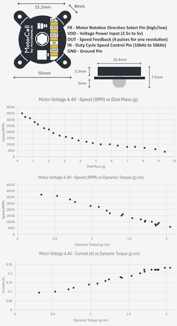
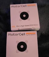
This is a fantastic setup for a low power application. With very little effort, you have a 5W 5V dc motor with a PWM controlled speed.
Being a tinkerer myself, This has been a wonderful starting point for a more specialized application range.
Thank you! Glad to hear the setup worked well for your low-power project. Enjoy building!
Just amazing. It is such a good quality and over just feels good. It has lasted me months because like most other screwdrivers the tips don't shread. Definitely worth so much money getting it Imported into india, also amazing for the actual price (not including importing and shipping but including them it's still soo good) i didget a few other things Atwell btw I bought from them when they were still a small business but just forgot to review but I got and email many months later asking me to review it and I just had to. 7 outta 5 stars would buy again.
Thank you so much for the amazing review! We're really happy to hear the screwdriver has held up so well and that the quality was worth the import costs. It means a lot that you’ve supported us since the early days — thank you!
I have been experimenting with making butterfly wings out of brass shim stock and powering the with a pair of flaps.
That sounds like a really fun project! We’d love to see how it turns out. Thanks for sharing and happy tinkering!
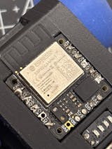
The CodeCell C3 is a great premium board. It has built-in light sensors and a BNO085 IMU, and the quality is really impressive. Everything feels solid and works perfectly. Highly recommended
Thank you for the great review! We’re really happy to hear you enjoyed the CodeCell C3! Glad everything worked perfectly for your project. Appreciate the recommendation!


