


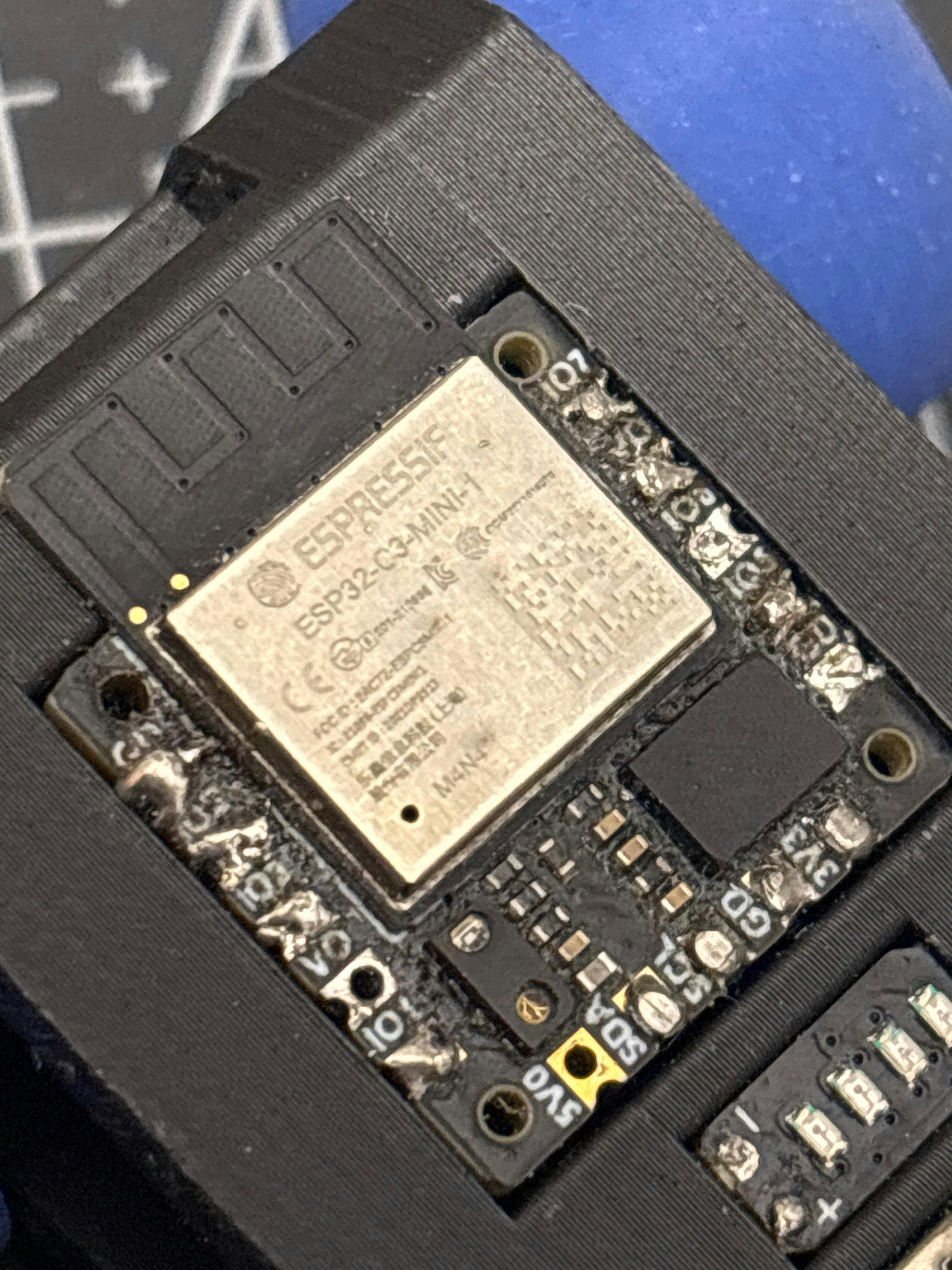
The CodeCell C3 is a great premium board. It has built-in light sensors and a BNO085 IMU, and the quality is really impressive. Everything feels solid and works perfectly. Highly recommended
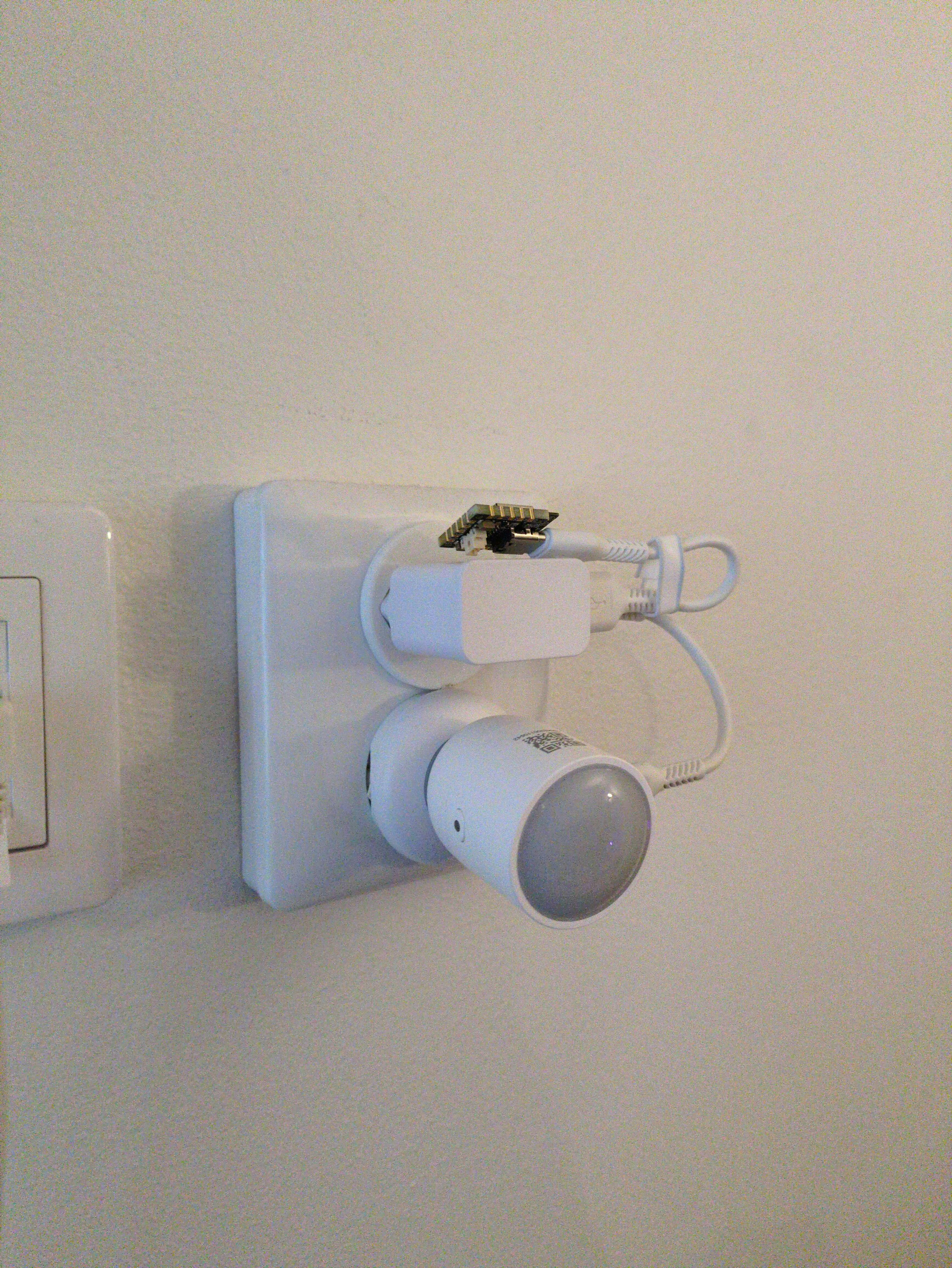
I have the basic ones around my house automating my lights (esphome + HA). I'll be buying more soon when we move into a larger place.
(I published the esphome lib on github)
Absolutely fantastic what can be done with the CodeCell C3.
Looking forward to do more projects with it.
Thank you for your positive review! We're glad to hear that you're enjoying using the CodeCell for your projects. We can't wait to see what else you create with it. Happy coding!
Nice Engineering
Thank you! We really appreciate it & we're glad you like the engineering behind our MotorCell!