


Great piece of kit, had just what i needed to complete the project i had in mind. Shame shipping to the UK is so expensive, but appreciate this isn’t necessarily in the hands of MicroBots
I had an issue, got a red light, I used too much flux. Support said clean it, then the one sensor worked fine. I got the help and answer same day I provided a foto.
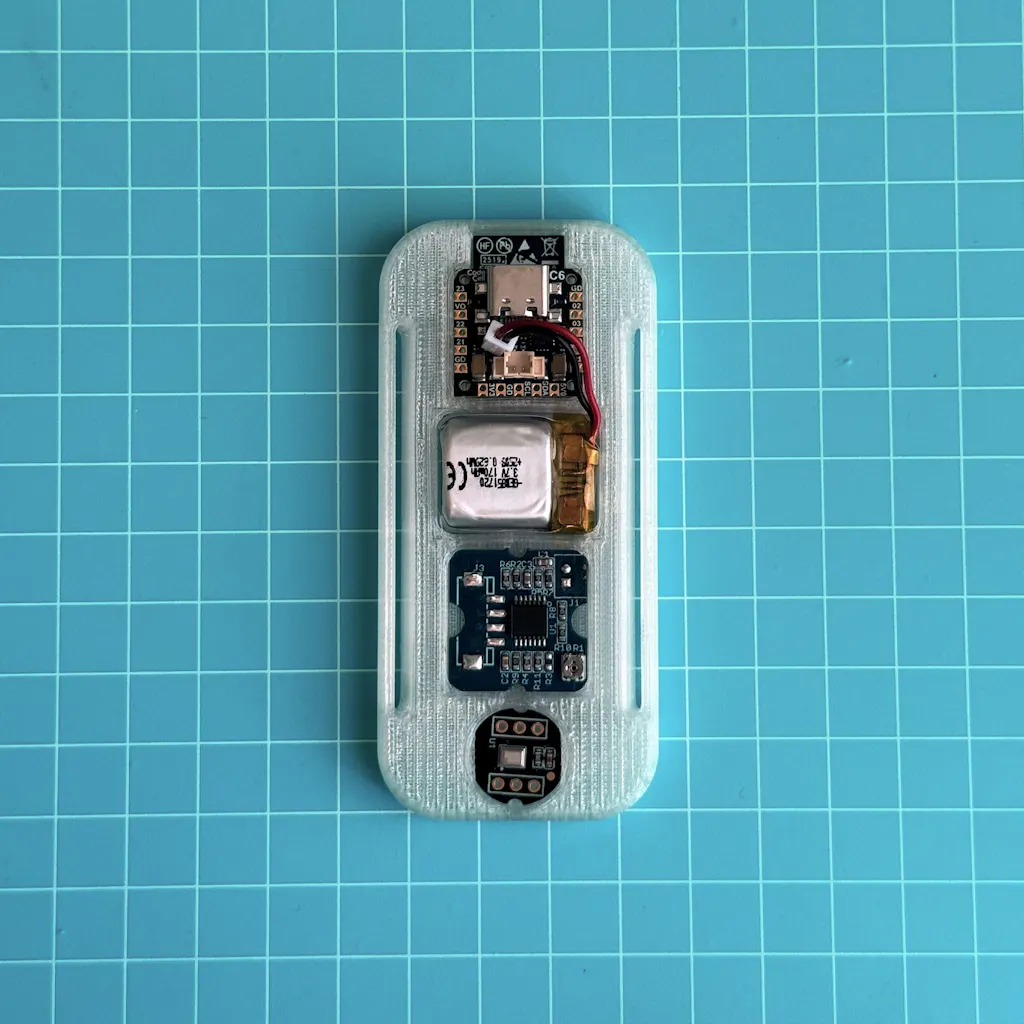
Been testing the Microbots CodeCell C6 and honestly impressed with how much functionality they packed into such a tiny module. Great form factor for rapid prototyping wearable/embedded sensing applications. ESP32-C6 + IMU integration makes development much easier compared to building everything from scratch.
Still exploring battery optimization and compact LiPo options for our use case, but overall the platform is promising for low-cost real-time sensing systems. Excited to keep building with it.